
Note: This post is part of a series. Each post builds on the previous ones. If you are just trying to add one thing to an existing system that was not built following this series, then I cannot promise that these instructions will work for you, although they probably will. If you’ve started from something other than a non-NOOBS Raspbian image, then you’ll probably need to adjust for that.
Please refer to the series Introduction for a list of all the different posts in the series.
Self-Promotion: I have recorded this series as a screencast for Pluralsight:
(http://www.pluralsight.com/courses/raspberry-pi-home-server)
If you have a Pluralsight subscription, please consider watching it. Reading the instructions is one thing, but watching it done demystifies the whole process.
Thank you!
My previous home “server” before embarking on this series was just an old laptop of mine. It wasn’t particularly strong, but it could run CrashPlan and serve files. One advantage it had was that, being a laptop, it had a built-in battery and knew how to shut itself down if the power went out. Of course, I had to go downstairs and start it back up once the power was restored, but at least nothing got corrupted.
If you have a desktop computer at home or at work, you may also have an Uninterruptable Power Supply (UPS) under your desk. This is basically a battery big enough to power your computer and monitor long enough for you to save what you are doing and shut down gracefully. Most modern UPS units also have a USB port on them and come with software so that when the power goes out, the UPS can tell the computer to automatically suspend, hibernate, or shut itself down depending on how you’ve configured it.
It shouldn’t surprise you that there are UPS options available for the Raspberry Pi as well. Take the CW2 “Pi UPS” (http://www.piups.net), for example. This product will work fine for most simple Raspberry Pi projects running off of an SD card, but my particular installation has a RAID enclosure hooked up to it. I don’t think AA batteries are going to cut it. What I need is something that will keep the hard drives spinning long enough for the Pi to shut down safely.
I’ve had my Raspberry Pi Home Server plugged into a UPS for well over a year now, and it survives power outages just fine, shutting itself down safely, and restarting automatically. My Raspberry Pi Home Server is attached to a CyberPower SX550G. I chose this model because:
- It has a USB connection to the computer.
- It was on sale for $40.
- I’m cheap.
It’s a 550VA battery backup, which probably wouldn’t get you very far with a full-sized desktop computer, but it should be more than adequate for a Router, a Raspberry Pi, and a couple of drives. It could probably run those devices for a good couple of hours if needed, actually. I haven’t done the math, but if not for the external drives, it could probably run the Pi for days.
So how can we get the Pi to use it intelligently? It certainly didn’t come with a ready-made software package for the Pi, although Linux software is available for it.
Network UPS Tools (NUT)
The Network UPS Tools package, aka “NUT” (http://www.networkupstools.org), is a collection of programs meant to make UPS hardware from different manufacturers work in roughly the same way. It’s available for a wide variety of platforms, one of which happens to be Debian Linux, of which Raspbian is a variant.
NUT consists of three major components
- A driver to communicate with your particular UPS using whatever protocol it supports, and translate that into a common API.
- A daemon (service) that connects via the driver and acts as a communication hub.
- A client program that can perform various tasks such as shutting down the computer when the power state reported by the daemon own sitechanges.
There are a few other components, such as command-line utilities that can tell you about the current state of the UPS, or allow you to make changes to the UPS configuration. For the most part though, we’re only concerned with the three components I just mentioned.
Note: NUT works with a wide range of UPSes, but without owning one from each different manufacturer and/or vintage, I can’t create instructions specific to each model. Questions about how to get NUT working with your particular UPS are best addressed on the project’s own site, or its GitHub site. For the most part, though, they should all work the same way.
If your UPS is older, and doesn’t have a USB port, but has a 9-pin serial port, you are totally on your own. I tried to make an older serial-ported UPS work through an RS232/USB adapter, but as it turns out, the UPS didn’t actually communicate over the serial port. It just shorted two pins together to mean that everything was okay. Maybe you could hack something together using the GPIO pins. If so, you’re a better man than me.
Installing Network UPS Tools (NUT)
Simplicity itself. Like most things we’ve installed in this series, NUT is available through apt-get
sudo apt-get install nut
Select your driver
Find the driver for your particular UPS by looking at the compatibility list on the NUT site (http://www.networkupstools.org/stable-hcl.html). If you can purchase a UPS that’s on the list, then that’s great. If you don’t find your UPS on the list, that doesn’t mean it won’t work, though. For instance, my UPS isn’t on the list, but a ton of other devices from the same company are, and they all seem to use the same driver (usbhid-ups). I gave it a shot, and it works just fine. YMMV
Configure the UPS
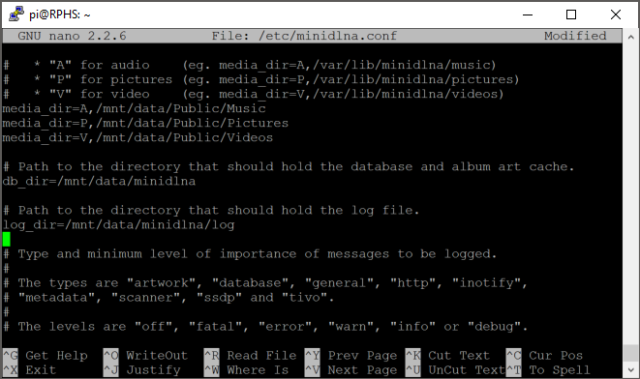
Once you’ve identified the driver for your UPS, you’ll need to edit the ups configuration file.
sudo nano /etc/nut/ups.conf
This file, like all of the NUT configuration files, is very well documented inline, and explains all of its different options. At the bottom of the file, you’ll add an entry for your UPS. You’ll need to give it a name, specify a driver, and give it a description. There is also an option to specify a port. For units that connect via a USB cable, this is meaningless, but it’s still required, so use the value “auto”.
[RPHS]
    driver = usbhid-ups
    port = auto
    desc = "CyberPower SX550G"
The name in square brackets is so you can tell multiple UPS devices apart in case you have one NUT server monitoring multiple devices. Unless you’re building something really esoteric, you probably only have one UPS like me, so for lack of anything better to call it, I’ve named mine “RPHS” after the computer it serves. You can put anything you want in the description, so I just put the make and model of the device for reference. The end result should look something like this:

That’s it for configuring the UPS itself. Close and save the file (ctrl-x, y, enter).
Configure the daemon
A daemon is the Unix/Linux term for any invisible background process. Windows folks call these “services”. For NUT, there is a daemon that is in charge of listening to the UPS via the driver, and telling the client applications what to do. Edit its configuration file like this:
sudo nano /etc/nut/nut.conf
For this simple application, where both the client and the server programs will be on the same computer (the Pi), go to the bottom of the file and set the MODE to “standalone”.

Close and save the file.
Verify hardware configuration
To check whether the driver and daemon are configured correctly, you can simply start up the service.
sudo upsdrvctl start
The first time I tried to connect to the UPS I got the error “could not detach kernel driver from interface 0: Operation not permitted”. I rebooted and tried again, and everything was fine.
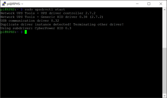
Notice that this time I got a message about “Duplicate driver instance detected”. This is because now that I have things configured correctly, the driver started up automatically when I rebooted. Not only that, but the daemon should be running now as well. Check it like this:
sudo service nut-server status
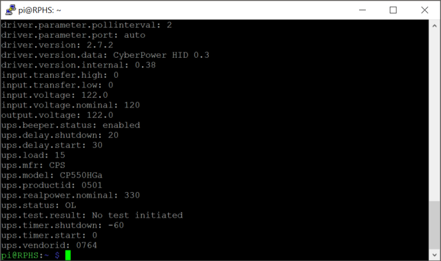
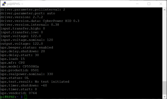
You should get a message that the NUT server is running. You can now ask the NUT server questions about the status of the UPS using “upsc”, one of several command line utilities that apt-get installed. Substitute the name you gave your UPS above as needed.
upsc rphs
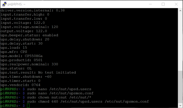
You’ll get quite a long list of information about the configuration and status of your UPS.

Depending on the make and model, you’ll get more or less detailed information.
Configure the monitor
That’s two out of the three layers. Last but certainly not least is the “upsmon” client. This is the part that will actually shut down the computer when the NUT server says so.
Define credentials that the monitor client program will use to connect to the server.
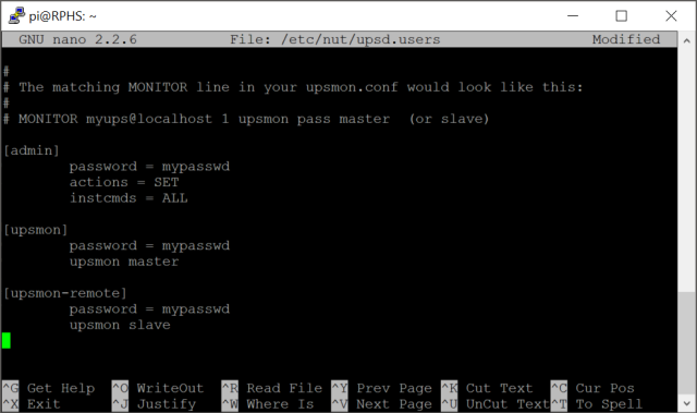
sudo nano /etc/nut/upsd.users
Go to the bottom and define two users, one called “admin” and one called “upsmon”. You can actually name them anything you want, but naming the “monitor” user after the program that will use it (upsmon), seems to be the convention. You give the “admin” user rights to issue commands and change configurations with the “actions” and “instcmds” settings. The “upsmon” user has no such rights, it’s just there to listen and shut the computer down when the power goes out.
[admin]
    password = mypasswd
    actions = SET
    instcmds = ALL

[upsmon]
    password = mypasswd
    upsmon master

Since this is the computer that’s actually in charge of monitoring the UPS, set the “upsmon” setting to “master”.
Next, edit the configuration file for the upsmon client program.
sudo nano /etc/nut/upsmon.conf
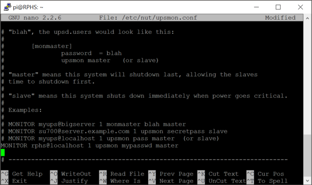
This configuration file is pretty long, and has a lot of options. The one we’re interested in is about five pages down. Look for the example lines that start with “MONITOR”, and create a new entry on the blank line below that section. There are six parts to this setting.
- The keyword “MONITOR”. It does have to be all uppercase, by the way.
- The “system” name in the format UpsName@HostName. I called my UPS “RPHS”, and since we’re running in standalone mode, we can just use “localhost” for the host name, so the resulting “system name” is “RPHS@localhost”.
- The “power value”. This only applies to big servers with multiple redundant power supplies. Just set it to “1”.
- The user name that you established in the upsd.users file (upsmon) .
- The password that you established in the upsd.users file (mypasswd).
- A value indicating whether this computer is the master or slave. You can read about the distinction in the upsmon.conf file itself, but for a standalone system like this, use “master”.
When you’re done, it should look something like this.
This next part is optional, but handy for testing that your system is working. Scroll down a bit further, and look for the NOTIFYFLAG section. There are two entries there, “ONLINE” and “ONBATT”, but they seem to be commented out by default in the current installation. Remove the pound sign from the beginning of these two lines, so that NUT can tell us about the state of the UPS when it changes.
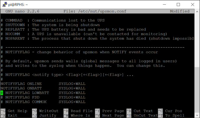
Close and save the file.
Next up, a little permissions wrangling. You need to set up the various configuration files to be readable by the NUT components that use them, but not by other users. This prevents anyone from reading the password, and sending unauthorized commands to the server to shut everything down. It may be overkill for a simple home network, but it’s also really simple to do.
sudo chown nut:nut /etc/nut/*
sudo chmod 640 /etc/nut/upsd.users /etc/nut/upsmon.conf
You should get no complaints
UPS Commands
Depending on the sophistication of your particular UPS, you may be able to send it commands to do things like initiate a self-test, or simulate a power failure. You can get a list of what your particular UPS supports with
sudo upscmd -l rphs
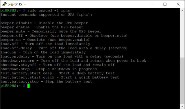
The number and type of commands will vary by manufacturer and model, so your output may not match mine. There are a few commands here worth mentioning, though. The “load.off” command will shut down the UPS immediately. Think of it as the “goodbye world” command. You generally don’t want to mess with that one. You could actually use this command to turn a second UPS on and off, allowing your Pi to control the power to something else. I’ll leave that one up to your imagination, but there are certainly cheaper ways to automate things.
The “beeper.mute” command will temporarily silence the warning beep that my UPS makes when the power goes out. This will make testing the system a bit less annoying here in the next section. The “beeper.disable” command would probably have the same effect, but on a more permanent basis.
Testing the system
Restart the NUT service and client daemons to ensure that they load all of the configuration changes we’ve made.
sudo service nut-server restart
sudo service nut-client restart
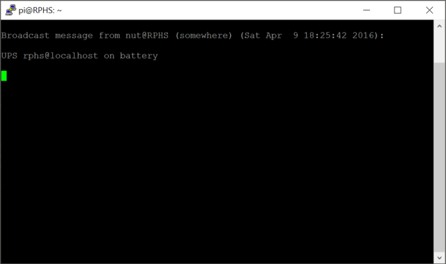
At this point, you can unplug your UPS from the wall and, after a short delay, you should get a message that the system is now running on battery power.
IMPORTANT: Wall messages like this don’t seem to show up in Terminal windows on the desktop. If you want to test this part for yourself, connect via SSH using a program like PuTTY on Windows.
If you plug it back in, you’ll get another message that power has been restored.

So far, so good. Now for the real test. Unplug the UPS from the wall and leave it unplugged. If your UPS supports it, now is a good time to issue that “beeper.mute” command. In my case, I issued the “upscmd rphs beeper.mute” command, and was prompted for a user name and password. We established the user name “admin” in the config file above.

You can sit and stare at the screen, wondering when it will shut down, or you can periodically check on the status to see how fast you’re using up the battery. I plugged my laptop charger and a television into the UPS to speed things along. A good, old-fashioned 100-Watt bulb would help, too.
Eventually, when the battery gets low enough, the system should shut itself down.
Plug the UPS back in, and if you’re lucky, everything will start back up again. For some models, even after the power is restored, you may have to physically press a button on the UPS to start everything back up. Mine starts up on its own, so a few minutes later I was back up and running.
Email notifications (optional)
Wall messages are just fine if you’re connected via SSH or looking at a monitor connected directly to the Pi, but if your server is headless or you’re running the desktop, you won’t see them. We need a way to be notified when something goes wrong. NUT can be configured to call any arbitrary command when it has something to say, so we’re going to set it up to send out email messages. This can inform you of power issues even when you’re not connected to the Pi at all.
We’re going to need to install a couple utilities to make this happen. I’ll be using ssmtp because it’s the simplest thing that works. Because it only knows how to send emails, it doesn’t leave any services running in the background using up CPU time. If you’ve already configured some other kind of mail agent on your system, then you’ll need to adjust accordingly.
sudo apt-get install ssmtp mailutils
Next, we’ll edit ssmtp’s configuration:
sudo nano /etc/ssmtp/ssmtp.conf
For this demonstration, I’ll be configuring ssmtp to work with gmail. If you want to use your ISP’s email services, then check out the ssmtp documentation, but most of the concepts should be the same.
Change the “mailhub” setting to point to your email server. For gmail, that will be “smtp.gmail.com:587”. For gmail, you’ll also need to add the “UseSTARTTLS=YES” setting. Scroll to the bottom of the file and add settings for “AuthUser”, “AuthPass”, and uncomment the “FromLineOverride”. The result should look something like this:
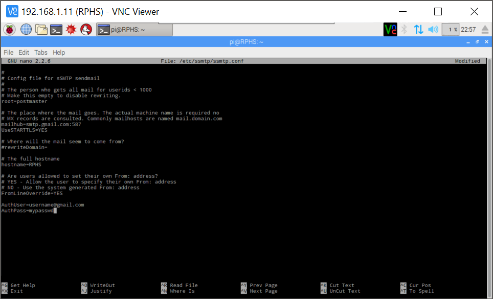
Note: If you have two-factor authentication set up with gmail, then the AuthPass setting will need to be an application-specific password. You can read more about that here.
Test your email setup by sending yourself an email from the command line.
echo "Test body" | mail -s "Test subject" [YOUREMAILADDRESS]
Check your inbox for the email. If you get it, then you’re ready to configure NUT to use ssmtp. Some wireless providers have special email addresses you can use to send texts to your phone. I have configured my NUT installation to send me texts rather than plain old emails, so I’ll notice them immediately.
Next, edit the NUT client configuration one more time to set up the email notifications.
sudo nano /etc/nut/upsmon.conf
Scroll down to find the NOTIFYCMD section, and add a line that says
NOTIFYCMD /etc/nut/upssched-cmd.sh
You presumably don’t want to be notified about every single power event that happens, so scroll down to the NOTIFYFLAGS section again, and add “+EXEC” to the end of the messages you want to receive emails for. I’m going to enable emails for the ONLINE and ONBATT events. The end result looks like this:

All that’s left is to create the script that we named in the NOTIFYCMD setting, “upssched-cmd.sh”.
sudo nano /etc/nut/upssched-cmd.sh
Paste in the following, substituting the email address where you want the notifications to go.
#!/bin/sh
echo "$*" | mail -s "Message from RPHS" [YOUREMAILADDRESS]
Exit Nano, saving the file (Ctrl-X,Y), and make it executable.
sudo chown nut:nut /etc/nut/upssched-cmd.sh
sudo chmod 700 /etc/nut/upssched-cmd.sh
Test the new script by calling it in the same way that NUT will in the event of a power event.
sudo /etc/nut/upssched-cmd.sh "This is a test message"
If you got that message, then everything is configured. Restart the NUT client so that it will pick up on the configuration changes.
sudo service nut-client restart
And now you can test the system again by unplugging the UPS from the wall. If everything is configured correctly, you should get an email (or text message) telling you that the power has gone out. Plug the UPS back in, and you should get another message telling you about it. Now you’ll know about power problems even when you’re not at home.
Adding more Pis to the same UPS (optional)
With Raspberry Pis being so cheap, you may very well have more than one. Perhaps you’ve split CrashPlan or MiniDLNA off onto a Pi all by itself. Maybe you went a little crazy and built a Pi-powered super-computer cluster. If, for any of these reasons, you have multiple Pis, and you’d like them to share the same UPS, how will they all know when the power’s gone out? After all, you can only plug the USB cable into one of them, and buying a separate UPS for each Pi would be overkill, right?
The great thing about NUT being split up into layers is that you can run multiple client instances against one server. Normally, this is the sort of thing you’d only see in a large server rack, where you’ve assigned one computer to watch the battery and tell all the others when the power goes out. It’s not the sort of thing regular home users usually care about, but Raspberry Pi owners are not regular home users.
If you do happen to have multiple Pis, getting them all to share a single UPS and shut down gracefully is actually really simple.
Reconfigure NUT on the server
Earlier, we configured NUT in “standalone” mode, which means that the server and client were on the same machine. It also means that the server isn’t expecting any other clients to be talking to it, so it simply isn’t listening for them. With a little bit of reconfiguration, we can tell the NUT server to listen for clients other than itself.
Edit the NUT configuration file.
sudo nano /etc/nut/nut.conf
Scroll down to the bottom, and change the mode from “standalone” to “netserver” (not “nutsever”, mind you).
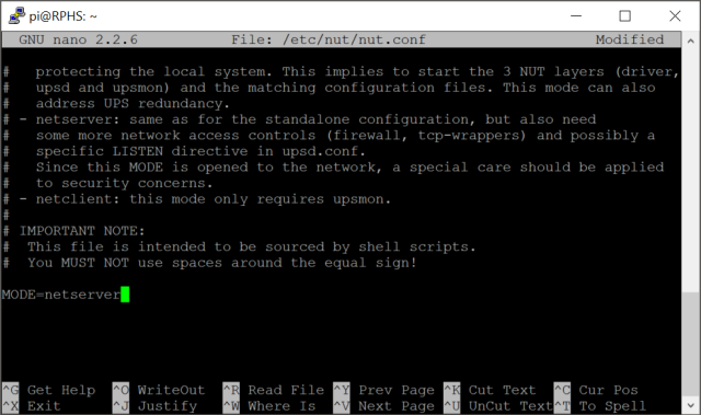
Close and save the file (ctrl-x, y, enter)
Next, you’ll need to configure credentials for the remote machines to use when connecting to the server.
sudo nano /etc/nut/upsd.users
Add a new user at the bottom. You can call it anything you like, but I’ve chosen “upsmon-remote”. Give it a password, and specify that it is a upsmon slave.
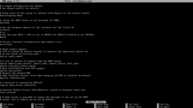
Next, you need to tell the NUT server to listen for client connections. Edit the UPS daemon configuration file.
sudo nano /etc/nut/upsd.conf
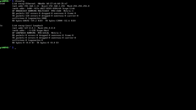
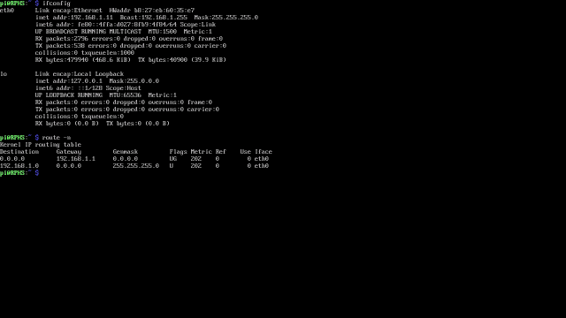
Find the “listen” section, and add a listen directive using the IP address of your server. If you don’t configure anything, the NUT server will listen only to the computer that it’s on, which is localhost, or IP address 127.0.0.1. Since you now want NUT to listen for clients on other systems as well, you’ll need to specify a real IP address.
Adding the server’s own IP address might seem a little redundant, but remember that NUT is made to work on all kinds of equipment, and it’s very common for larger-scale servers to have multiple network interface cards, and you’d only want it to listen for NUT traffic on the “inward” facing one.
Because you will still want to run a ups monitoring client locally on the server itself, and you’ve now overridden the defaults by specifying one IP address, you’ll need to explicitly add an entry for localhost (127.0.0.1) back in as well, otherwise the local ups monitor will stop working. The result should look something like this:
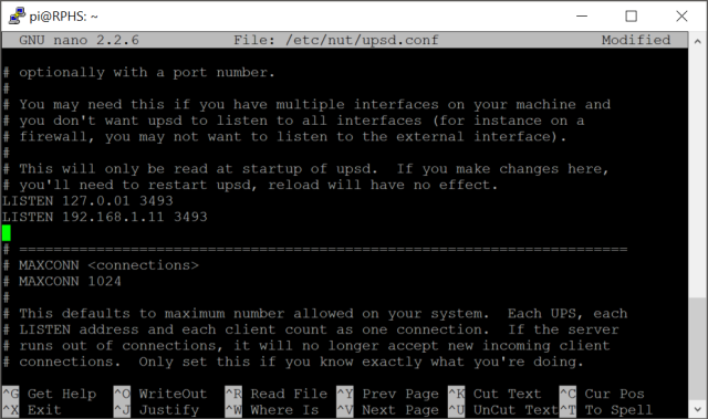
Note: You’ll need to substitute your own Pi’s address in place of 192.168.1.11. That’s just the address where my own Pi server lives. The default port that NUT listens to is 3493. If you wanted to change that, for some reason, you would do that here. I’m going to leave it at the default port, though.
Reboot the server to get things reconfigured and restarted.
sudo reboot
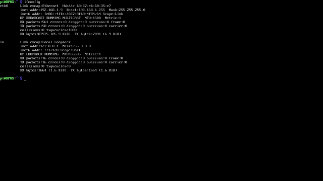
Double check that you can still communicate with the NUT locally:
sudo upsc rphs
You should get the same kind of listing of UPS settings and status as you did in standalone mode:
If you get some kind of error instead, make sure that you added an entry for localhost (127.0.0.1) in addition to the Pi’s regular IP address.
You can actually run NUT configured this way, but without any clients connected, and it will behave in pretty much the same way as it did in standalone mode, but it will still be listening for additional clients over the network.
Configure the client machines
Install NUT on each additional Pi that you intend to run from the UPS.
sudo apt-get install nut
For these additional client-only installations, you can skip configuring a UPS driver and proceed directly to configuring the client.
sudo nano /etc/nut/nut.conf
Go to the bottom of the file, and set MODE to “netclient”.
Next, edit the upsmon configuration file.
sudo nano /etc/nut/upsmon.conf
This time, configure the client to talk to the remote server for information, and configure it as a slave. This time, the “system name” will not be “RPHS@localhost”, but “RPHS@192.168.1.11” (again, substitute your server’s IP address).
If you remember from earlier, the first part of this “system name” is the name you gave your UPS, and the second part is the address of the server it’s attached to. The name and password should match the “upsmon-remote” name and password from above, and the final parameter will be “slave” instead of “master”. The result should look like this:
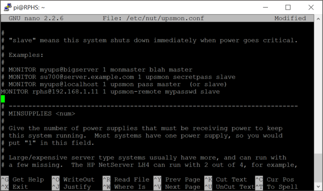
Note: My other Pis are all busy right now, so I’m doing the edits (but not saving them) on my original server for these screenshots. Please ignore the name in the title bar.
The difference between “master” and “slave” has to do with when each one will shut down. When the UPS says the power has dipped below the safe threshold (20% for my UPS), the server (the master), will tell all of the clients (the slaves) to shut down first before shutting down itself.
Like on the server, you’ll need to set up the permissions so that the NUT configuration files are readable by the nut user. Unlike the server, however, you don’t need to touch the upsd.users file because users are defined on the server, not the client.
sudo chown nut:nut /etc/nut/*
sudo chmod 640 /etc/nut/upsmon.conf
Check connectivity
From the slave system, you can issue the same kinds of commands you could run from the master system. Use this to verify that everything is communicating properly.
sudo upsc RPHS@192.168.1.11
I’ve used the IP address because name resolution didn’t work for me. It’s one of those things I’ll probably learn to set up someday, just not today.
Test the system
Once again, unplug the UPS, and you should see warning messages appear on both the server and client(s) right away. Again, you may want to mute the beeper if your hardware supports it, and plug something in to help the battery drain faster.
Apart from the name of the server sending the message, and the fact that the client shut down first, you wouldn’t be able to tell the difference between the client and server installations, even though only the server is actually attached to the UPS.
Lather, Rinse, Repeat
Repeat as necessary for each additional Raspberry Pi you are plugging in to the same UPS. That’s all there is to it. When the power goes out, all your Pis can now shut themselves down safely.
Wrapping up
You know the drill by now. Shut down the server, and back up the SD card.
What’s Next?
In the next post, we’ll reconfigure the Pi to boot from the hard drive instead of the SD card.


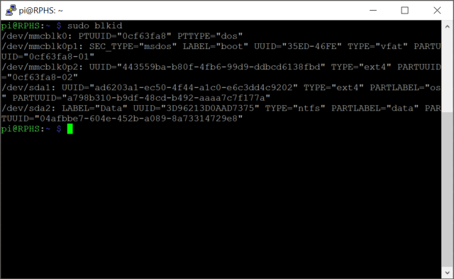
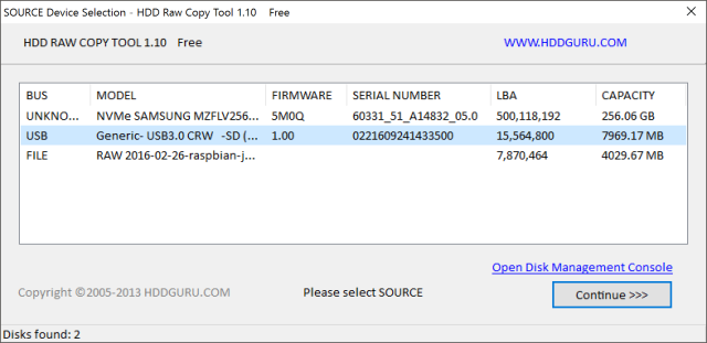
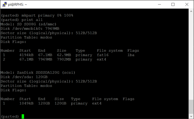 In my example, the second one is the external drive, although the order is not guaranteed here.


